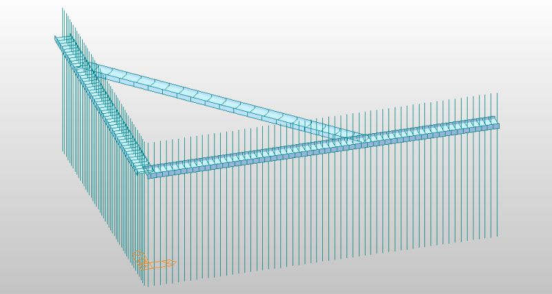
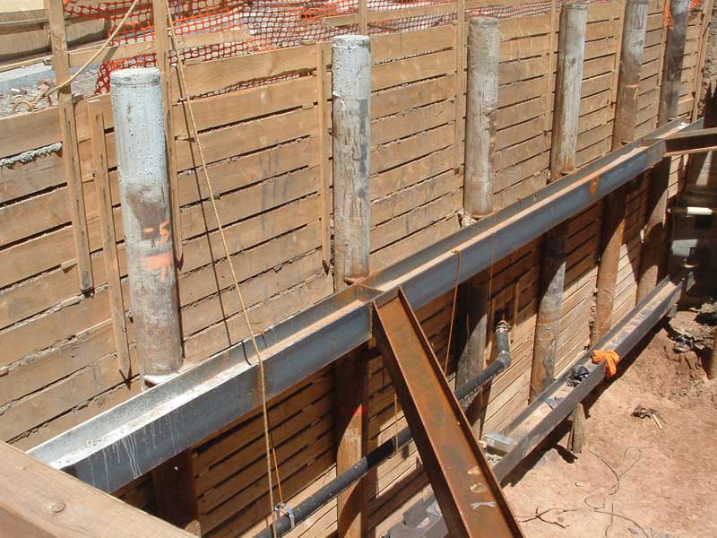
Sheet Pile Wall Waler Design

Vinyl Bulkhead Navy Wall Google Search Construction Composite Decking Sea Wall

Figure V 2 8 Shoring Variations Typical Aluminum Hydraulic Shoring Installations Excavation Site Plan Hydraulic

Westhollywoodretainingplan Png 1 620 1 080 Pixels Retaining Wall Pixel Sheet Music
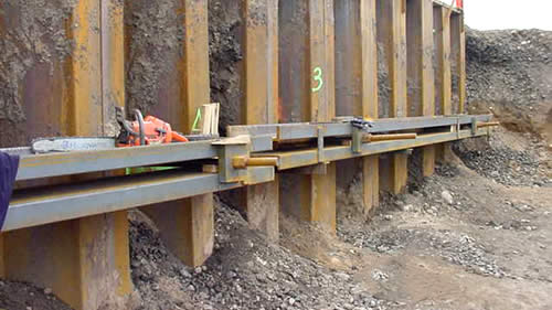
Sheet Piling Waler System Design Structural Engineering General Discussion Eng Tips

Zont Installation For Catwalk Over 6 Installation Insulated Concrete Forms Concrete Footings

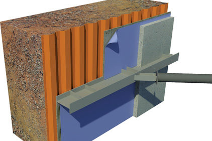
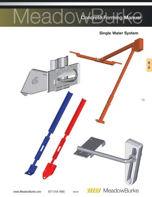
Waler

The waler system with its distributed load design has reduced the load on the concrete structure by 80.
Sheet pile wall waler design.
A Collaborative Approach To Temporary Earth Retention Systems For Foundations 2014 05 26 Building Enclosure

Strutting Systems Oriental Sheet Piling

The Project Managers Should Focus On Quality Control And Safety Associated With A Construction Project Flaws Or Failures In Construction Can Lead T Construccion
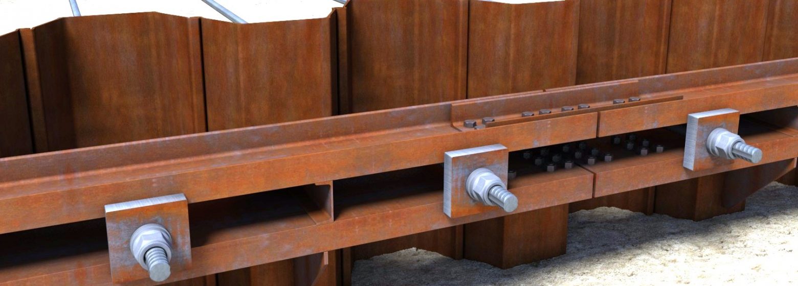
Anchors Struts Arcelormittal Steel Sheet Piles

Deadman Sheet Pile Wall Design In Colombia Deep Excavation
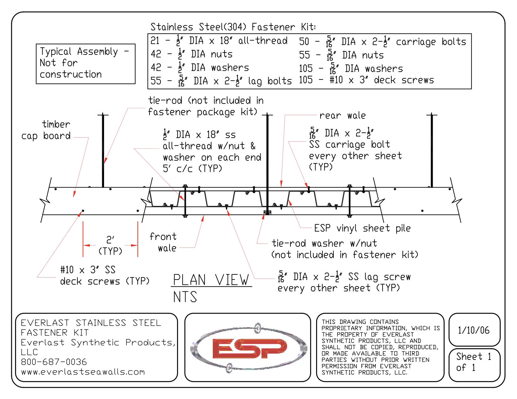
How To Build And Install A Seawall Everlast Synthetic Products

Podium Slabs Belong To Special Type Of Floor System The Purpose Of These Types Of Slabs Is To Transmit The Loads From A St Slab Types Of Flooring Construction
Constructing Basements To Receive Waterproofing Page 2 Of 4 Construction Specifier

What Is Self Compacting Concrete And How Is It Used Types Of Concrete Concrete Concrete Design

50ft Deep Excavation Design Example Deep Excavation
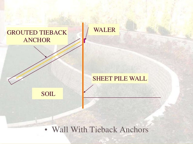
Retaining Wall
Simplified Model Of Strut Waler Support System For Retaining Wall In Download Scientific Diagram
Structural Sections Catanchorcompany Com

Analysis Methods In Deepex Deepex

Sheet Pile Walls Sheet Piles Sheet Pile Design Sheet Pile Software Deep Excavation

Temporary Works At 22 Hanover Square Swanton Consulting
Https Www Tandfonline Com Doi Pdf 10 1080 19373260 2012 700790

Installation Process Of Sheet Pile Wall Jembinaem
Https Encrypted Tbn0 Gstatic Com Images Q Tbn 3aand9gcq0venh1wrf9hobj8khwp Pyoapdc6 Pzr2pbgpqem Usqp Cau
Https Www Nipponsteel Com Product Catalog Download Pdf K007en Pdf

Shoring Systems Ausipile

Deep Soil Mixing For Retention Of Excavations Geoengineer Org
Snap Tie Wall Lay Out Rtm Supply

Developing A Numerical Model For The Design Of Sheet Pile Walls

Nasspa The Robb Partnerships

704 Steel Sheet Piling And Cofferdams Mdot Wiki
Soldier Pile And Lagging Wall Coastal Drilling East

Cofferdam Design Combined Sheet Pile Walls Lem Nl Fem Analysis Deepex

Walers And Struts Mgf Excavation Safety Solutions
Https Www Mesacounty Us Globalassets Public Works Bids Construction Pertinent Information State Highway 340 Auxiliary Left Turn Lane At Colonial Drive Project Ifb 19 03041 Colonial Final Plans Posted 11 12 2019 Pdf

Section 3 Creating A 2d Model With Deepex Deepex

Traditional Sheet Pile Shoring System For Trench Protection

Wall Bridge Mgf Excavation Safety Solutions
Http Www Mgf Ltd Uk Wp Content Themes Mgf Files Online Brochures Mgf 20corporate 20brochure Pdf

Retaining Wall Software Retaining Wall Design Software Deep Excavation
Http Naples Granicus Com Metaviewer Php View Id Clip Id 3042 Meta Id 209060
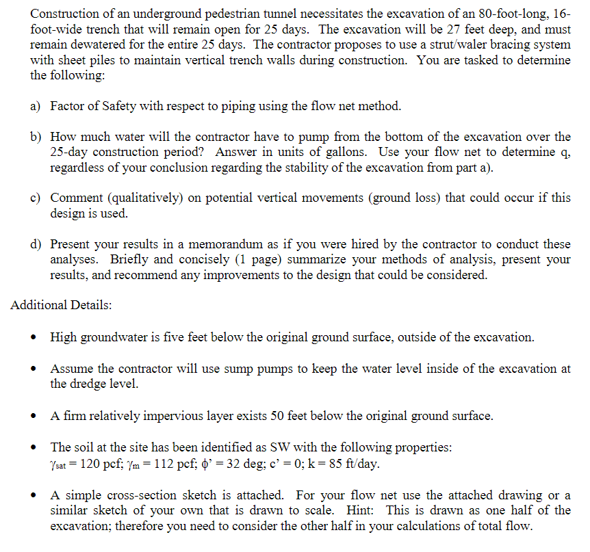
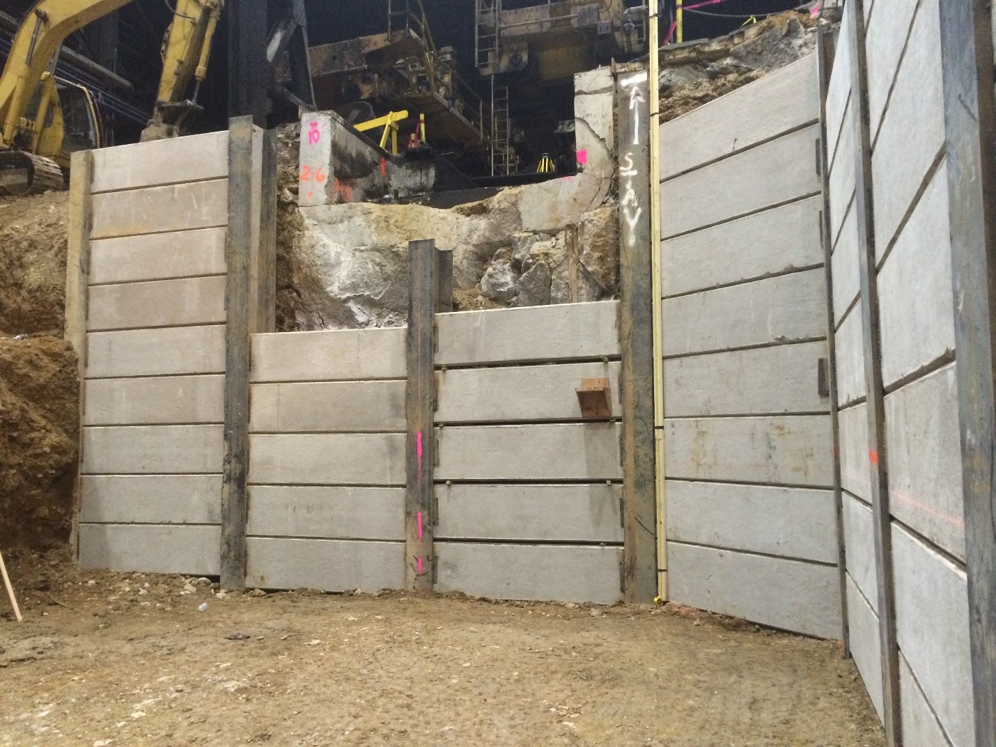
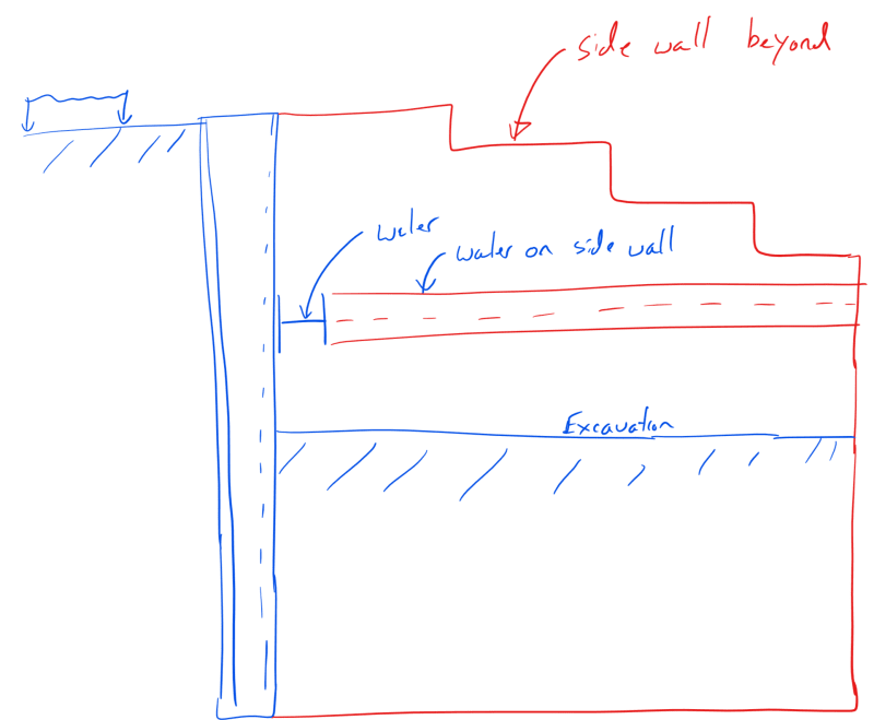
Construction Of An Underground Pedestrian Tunnel N Chegg Com

Sheet Pile Design Software Sheet Pile Design Deep Excavation

Cofferdam Cofferdam Design Cellular Cofferdams Deep Excavation
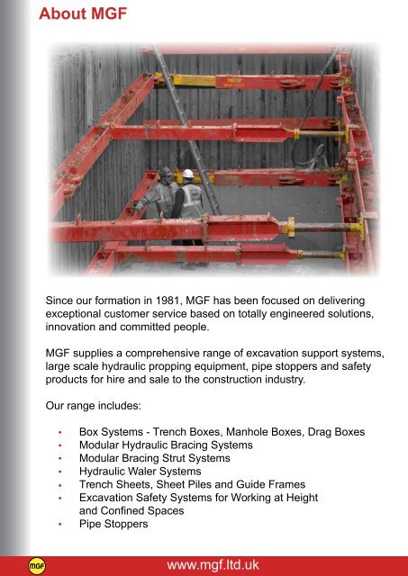
Section 1 Design Mgf Trench Construction Systems Ltd

Ptc Sheet Pile Wall Construction Youtube

Retaining Wall Builders Auckland Ground Structures

I Gewi I Tie Rods Secure Sheet Piling For Quay Wall Germany Dywidag Systems International Group
Three Sided Excavtion Again Earth Retention Engineering Eng Tips
Source : pinterest.com
